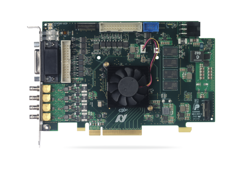
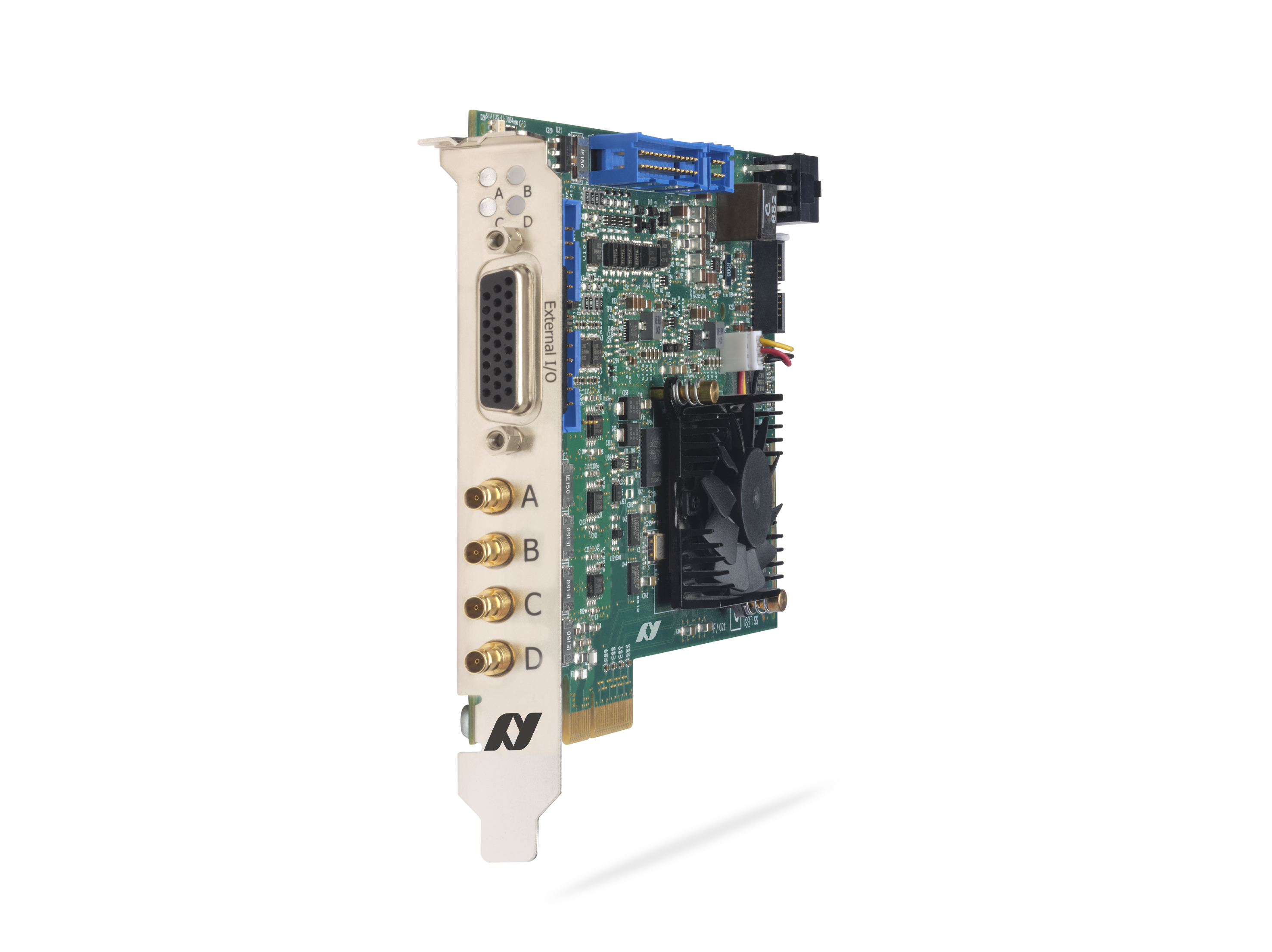
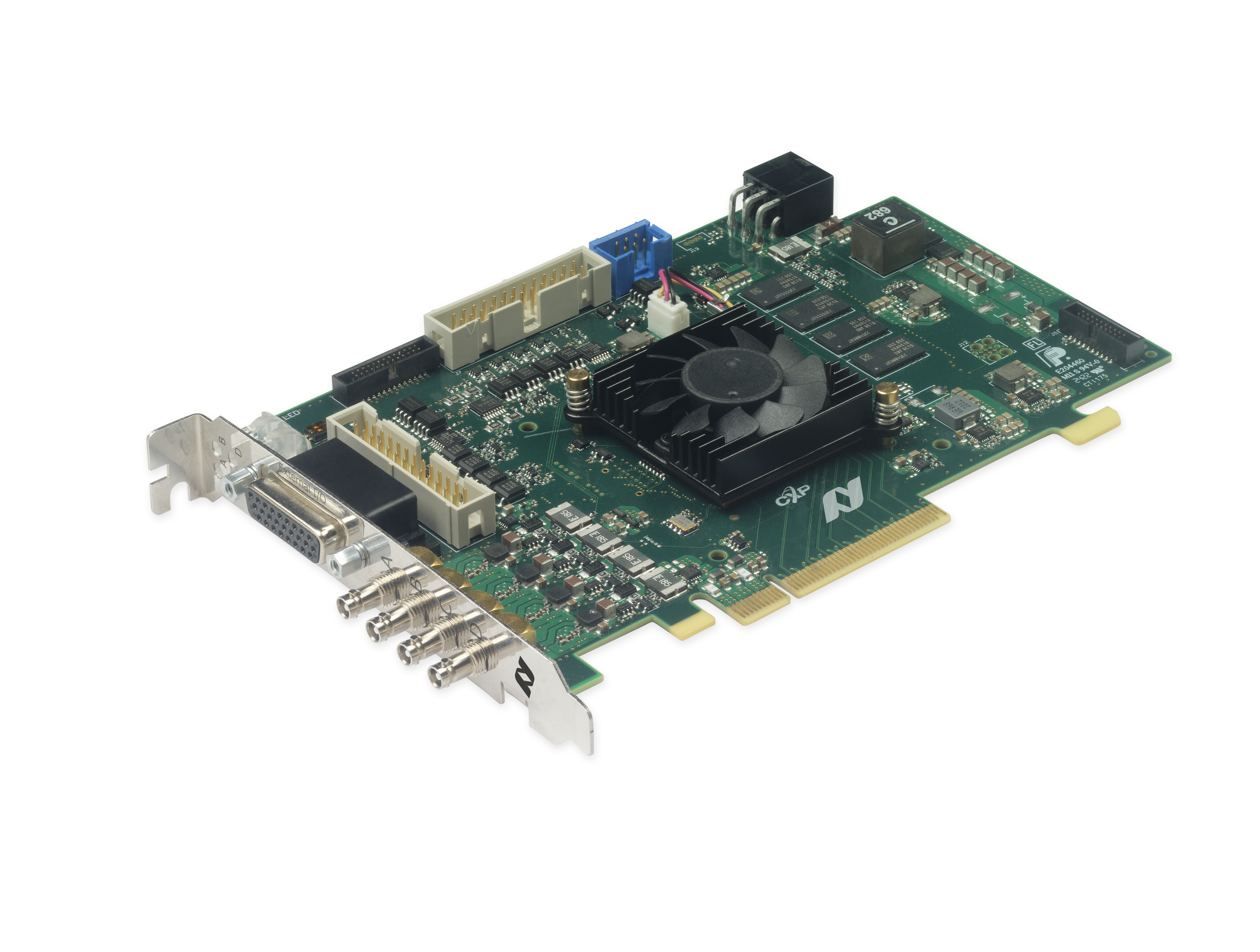
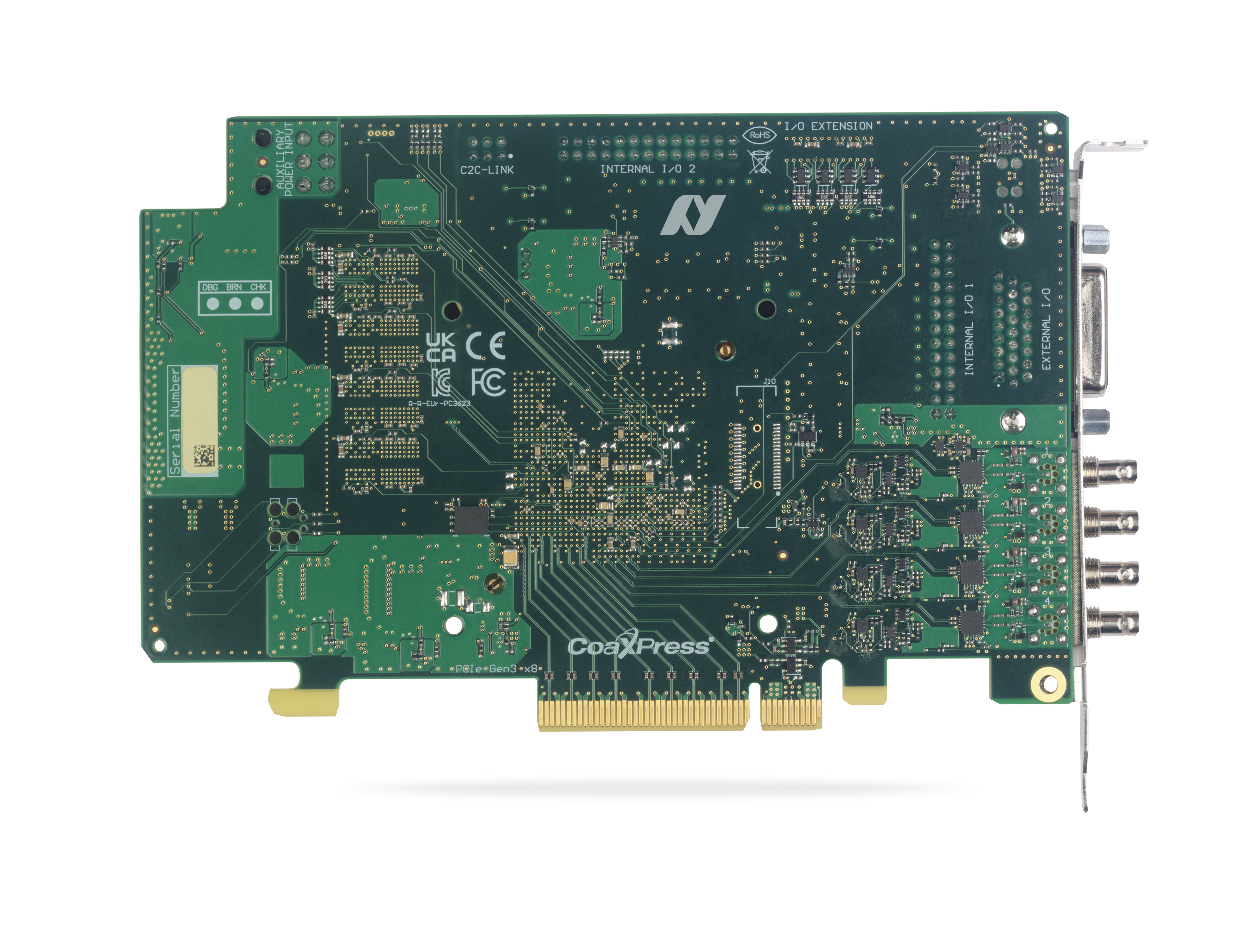
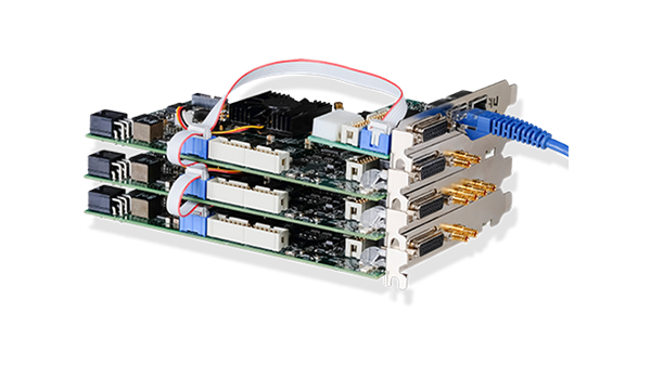
Coaxlink Quad CXP-12 超值
四連線 CoaXPress CXP-12 訊框擷取器
- 四個 CoaXPress CXP-12 連線:5,000 MB/秒的攝影機頻寬
- PCIe 3.0 (Gen 3) x8 匯流排:6,700 MB/秒匯流排頻寬
- 功能豐富的 20 組數位 I/O 線路
- 廣泛的攝影機控制功能
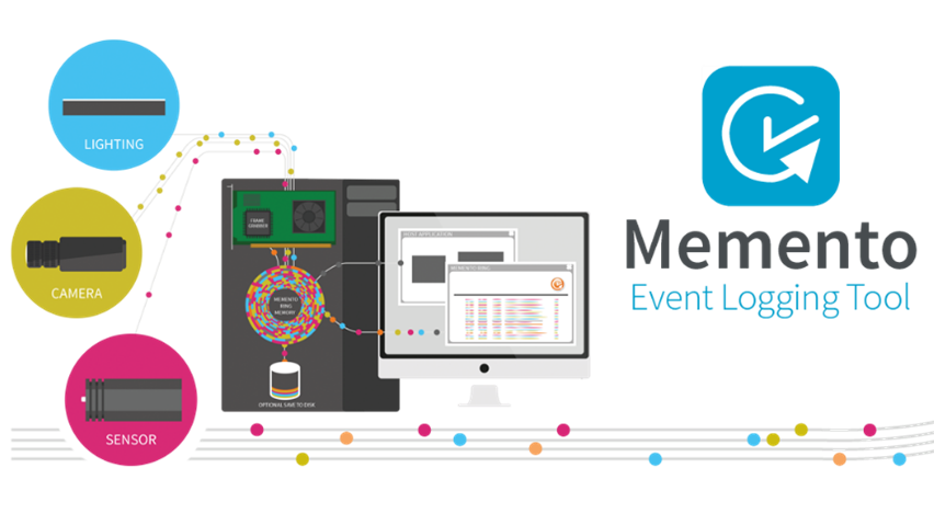
- Memento 事件日誌工具
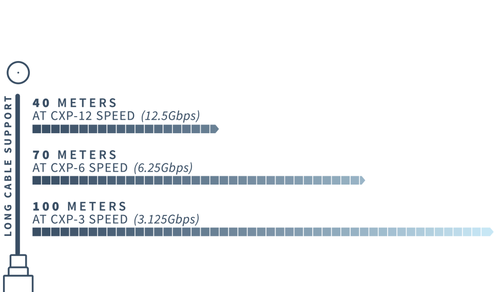
長纜線支撐
-
- 40 公尺(CXP-12 速度,12.5 Gbps)
- 以 CXP-6 速度(6.25 Gbps)傳輸 72 公尺
- CXP-3 速度(3 Gbps)下達 100 公尺
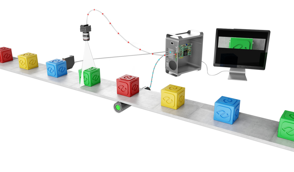
線性掃描觸發功能
Allied Vision 的影像擷取卡具備多種功能,可同步線掃描或 1D 相機、感測器及照明控制器。影像擷取卡能根據從運動編碼器接收的訊號,控制相機的掃描速率。
它們支援連續卷材掃描(用於檢測無限延伸且持續移動的表面,且不會遺漏任何一條掃描線),以及離散物體掃描(用於擷取在相機前方移動的物體影像)。
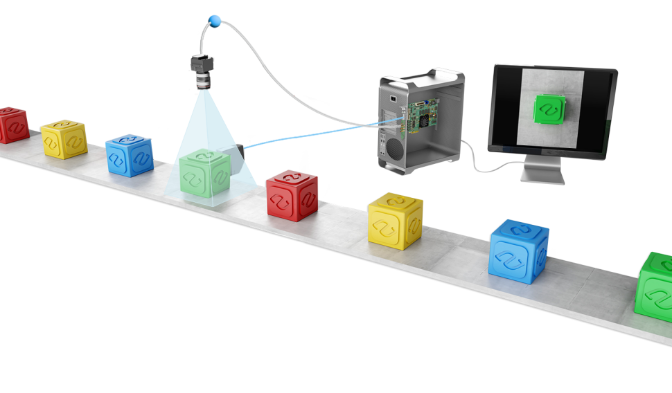
區域掃描觸發功能
Allied Vision 的影像擷取卡具備多種功能,可同步區域掃描或 2D 攝影機、感測器及照明控制器,適用於視野範圍內的靜態或動態物體,或移動中的攝影機。
優點
與 eGrabber 相容
-
-
eGrabber Studio:eGrabber 的互動式評估和演示應用程序,可存取 GenTL Producers 公開的 GenICam 功能。
-
GenTL Console:一個命令列工具,可存取 Euresys GenTL Producers 公開的功能和命令。
-
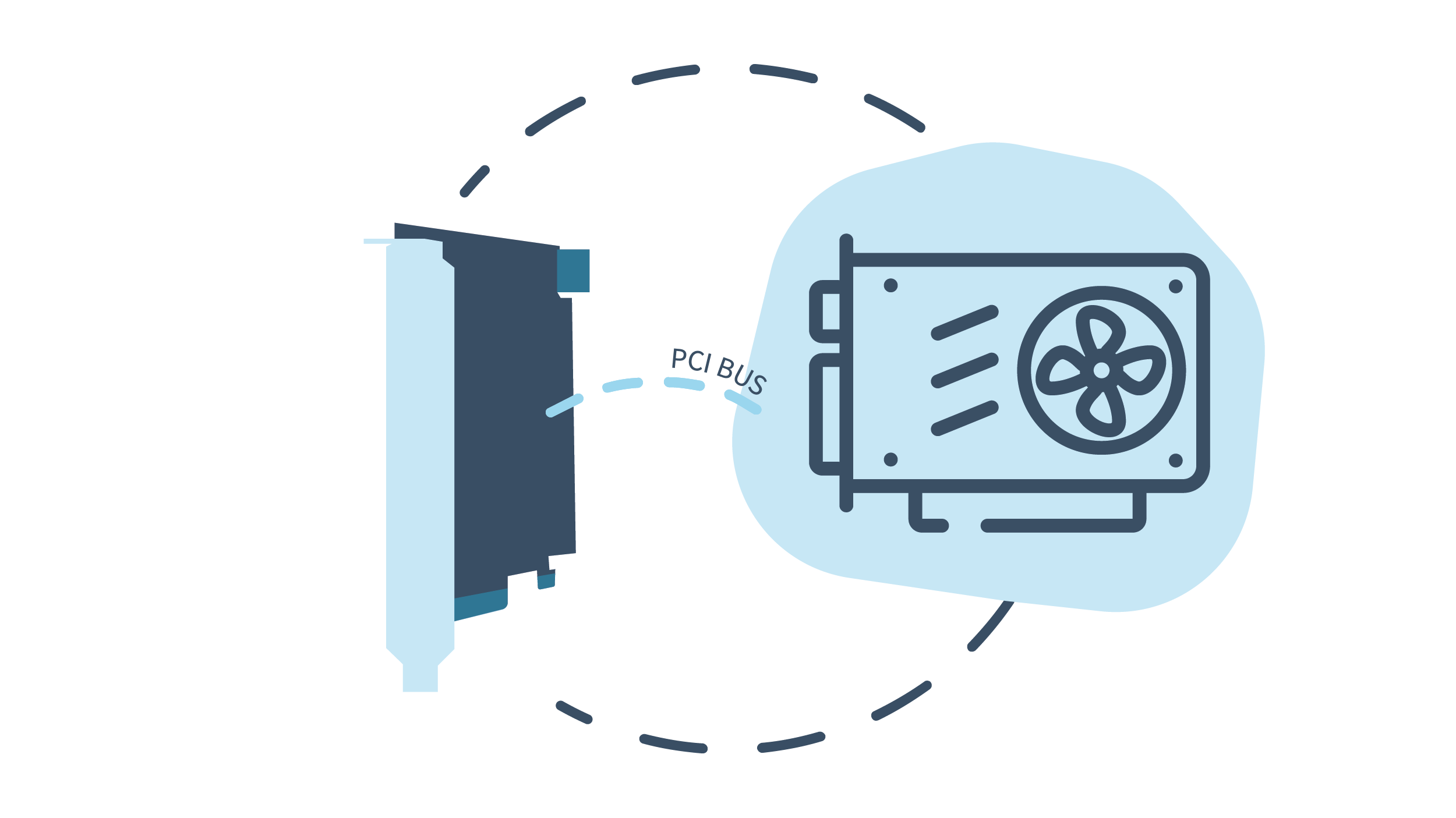
PCIe 3.0 (Gen 3) x8 匯流排
- 7,800 MB/s 峰值匯流排頻寬
- 6,700 MB/s 持續匯流排頻寬
與 GenICam 相容
包含對以下項目的支援:
-
- GenApi
- 標準功能命名規範 (SFNC)
- GenTL

Power Over CoaXPress
-
- 在 24 VDC 供電下,每通道可為您的攝影機提供高達 17 W 的電力,並具備自動裝置偵測、量測及過載保護功能。
- 可進行總電壓與電流測量,以及各通道的電壓與電流測量,以便進行驗證及監控性能偏差。
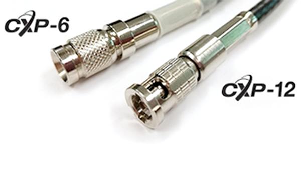
使用標準同軸電纜
-
- 一條經濟實惠的線纜,即可同時實現資料傳輸、攝影機控制、快門觸發及電源供應
- 具備頂尖的可靠性與靈活性,即使在最嚴苛的環境下也能穩定運作
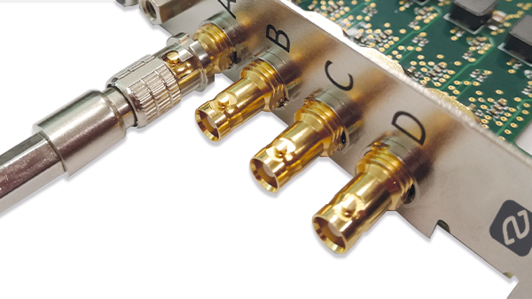
用於可靠連接的 Micro-BNC (HD-BNC™) 連接器
-
- 值得信賴的「推入並旋轉」卡口式正鎖設計
- 可快速輕鬆地連接與斷開
Memento 事件日誌工具
-
- Memento 是一款適用於 Coaxlink 和 Grablink 卡的高階開發與除錯工具。
- Memento 會精確記錄所有與攝影機、幀擷取卡及其驅動程式,以及應用程式相關的事件日誌。
- 它為開發人員提供帶有時間戳記事件的精確時間軸,並附帶上下文資訊和邏輯分析器視圖。
- 它在應用程式開發與除錯期間,以及機器運作期間,皆能提供極具價值的協助。
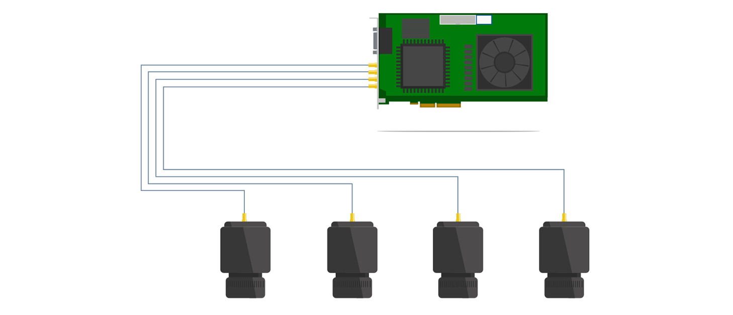
最多可將 4 部攝影機連接至單一同軸連接卡
單張 Coaxlink 卡最多可連接 4 台攝影機
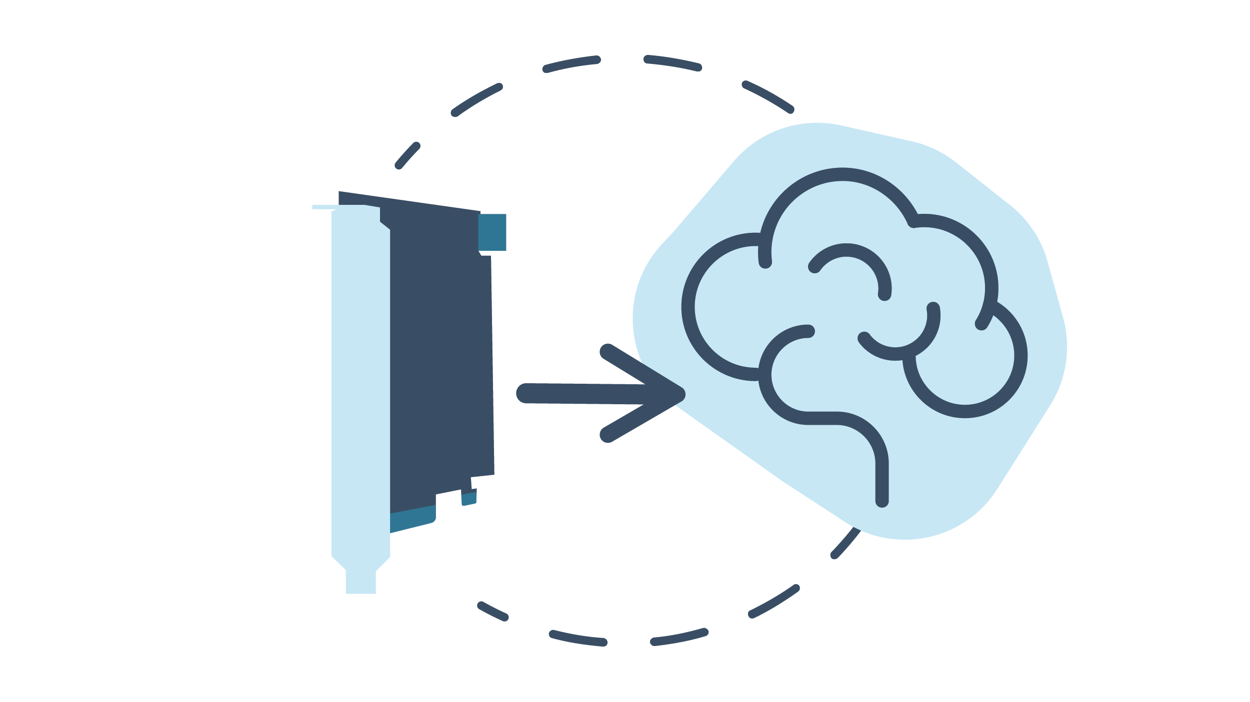
直接 GPU 傳輸
-
- 提供 AMD DirectGMA 和 NVIDIA (CUDA) 的範例程式。
- 直接 GPU 傳輸可消除不必要的系統記憶體複製,降低 CPU 開銷並減少延遲,從而顯著提升應用程式的資料傳輸效能。
- 透過 AMD 的 DirectGMA,可將影像資料直接擷取至 GPU 記憶體。相容於 AMD FirePro W5x00 及以上型號,以及所有 AMD FirePro S 系列產品。
高效能 DMA(直接記憶體存取)
-
- 直接傳輸至使用者分配的記憶體
- 硬體散射-匯集支援
C2C-Link 攝影機同步
可精確同步連接至同一張卡上的多台區域掃描或線性掃描攝影機
-
- 至同一張卡
- 至同一台電腦中的不同擴充卡
- 連接至不同電腦中的不同擴充卡
提供 Windows、Linux 和 macOS 驅動程式
包括對 Intel 64 位元平台以及 ARM 64 位元平台的支援。
線性掃描元資料插入
啟用此功能後,系統將在影像資料之外同步記錄元資料。每擷取一列影像,便會擷取對應的列元資料;至於緩衝區元資料,則僅在擷取緩衝區的第一列影像時進行記錄。這些元資料由一組可配置的通用事件計數器、正交編碼器位置計數器及/或 I/O 線路狀態組成。此功能使線掃描應用能將影像資料與系統事件(包括運動編碼器位置)建立關聯。
使用速率轉換器靈活操作線掃描攝影機
- 此頻率轉換器是一款智慧型、可程式化的頻率倍增器/分頻器。
- 配合運動編碼器與線掃描相機使用時,可讓使用者選擇影像中像素的長寬比。
- 它提供了一種校準影像擷取鏈的方法,可輕鬆實現正方形(1:1 長寬比)像素。
eGrabber
探索我們的幀擷取軟體

General
| Product name: | PC3623 Coaxlink Quad CXP-12 Value |
| Product code: | 3623 |
| Product status: | Released |
Mechanical
| Form factor: | PCIe Card |
| Cooling method: | Air cooling / fan-cooled |
Host Bus
| Standard: | PCIe 1.0 |
Camera Inputs
| Camera interface standard: | CoaXPress |